実装状況
PICマイコン用に設計された基板に、無理矢理AVRを取り付けたので、ジャンパ線ばっかりになっています。
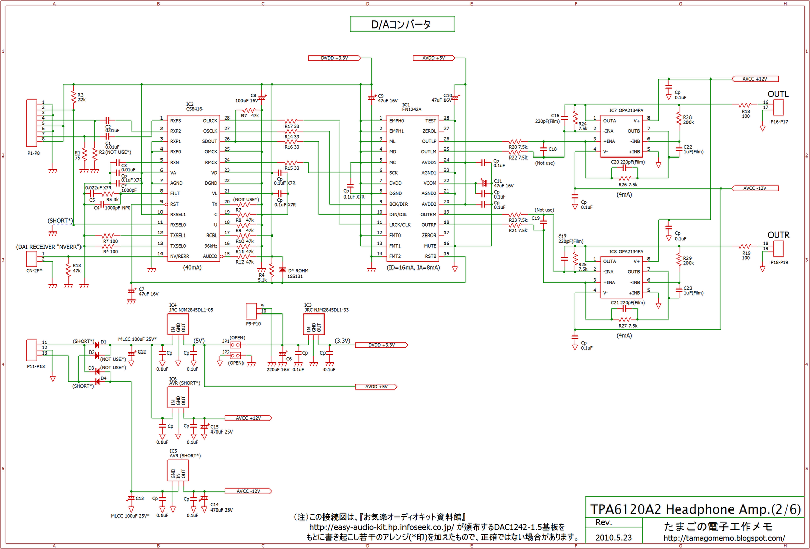
回路図

#include <avr/io.h>
#include <avr/interrupt.h>
#include <stdlib.h>
#include <avr/sleep.h>
#include <avr/pgmspace.h>
#include <inttypes.h>
#define I2C_FUNCTIONS
#include ”soft_I2C.h”
/*
PB5 I (Reset)
PB4 I DIP SW 1-1
PB3 I DIP SW 1-2
PB2 I/O SCL/(ISP SCK)
PB1 I/O (ISP MISO)
PB0 I/O SDA/(ISP MOSI)
*/
uint8_t I2C_comd(uint8_t cmd)
{
I2C_start_cond();
if( I2C_status_flag != 1) return(I2C_status_flag);
I2C_Master_send(Si570_ADR);
if( I2C_status_flag != 1) return(I2C_status_flag);
I2C_write(cmd);
if(I2C_status_flag !=1) return(I2C_status_flag);
return(1);
}
void I2C_put(uint8_t cmd, uint8_t data)
{
if( !(I2C_status_flag = I2C_comd(cmd)) ) return;
I2C_write(data);
if(I2C_status_flag != 1) return;
I2C_stop_cond();
}
void init_si570(void)
{
// Freeze DCO
I2C_put(137,0x10);
// Set HSDIV, N1, RFREQ
switch (((bit_is_clear(PINB,4))<<1) | (bit_is_clear(PINB,3))) {
case 0: // 122.880MHz
I2C_put(7, 0x21); // HSDIV=1, N1=7
I2C_put(8, 0xC2); // RFREQ=0x02B021DE77
I2C_put(9, 0xB0);
I2C_put(10, 0x21);
I2C_put(11, 0xDE);
I2C_put(12, 0x77);
break;
case 1: // 73.728MHz
I2C_put(7, 0xE1); // HSDIV=7, N1=5
I2C_put(8, 0x42); // RFREQ=0x02A9404015
I2C_put(9, 0xA9);
I2C_put(10, 0x40);
I2C_put(11, 0x40);
I2C_put(12, 0x15);
break;
case 2: // 61.440MHz
I2C_put(7, 0x23); // HSDIV=1, N1=15
I2C_put(8, 0xC2); // RFREQ=0x02B021DE77
I2C_put(9, 0xB0);
I2C_put(10, 0x21);
I2C_put(11, 0xDE);
I2C_put(12, 0x77);
break;
case 3: // 12.288MHz
I2C_put(7, 0xE8); // HSDIV=7, N1=35
I2C_put(8, 0xC2); // RFREQ=0x02A9404015
I2C_put(9, 0xA9);
I2C_put(10, 0x40);
I2C_put(11, 0x40);
I2C_put(12, 0x15);
break;
default: // 122.880MHz
I2C_put(7, 0x21); // HSDIV=1, N1=7
I2C_put(8, 0xC2); // RFREQ=0x02B021DE77
I2C_put(9, 0xB0);
I2C_put(10, 0x21);
I2C_put(11, 0xDE);
I2C_put(12, 0x77);
}
// UnFreeze DCO
I2C_put(137, 0x00);
// Set New Freq
I2C_put(135, 0x40);
}
int main(void)
{
// 出力ポート初期化
// 入力ポート、1:プルアップ
PORTB = 0b011101;
// ポート設定 0:入力, 1:出力
DDRB = 0b000101;
// USIインタフェースの初期化
I2C_Master_init();
// Si570の設定
init_si570();
while(1); // 無限ループ
}
//#include <avr/iotn861.h>
//#define I2C_FUNCTIONS
void I2C_Master_init()
{
// USIPP = I2C_USIPOS;
//#define RTC8564_ADR 0xA2 //8564 RTC
#define Si570_ADR 0xAA // Si570 I2C Address: 0x55<<1
#define I2C_PORT PORTB
#define I2C_PIN PINB
#define I2C_DDR DDRB
#define I2C_SDA PB0
#define I2C_SCL PB2
HSDIV
3ビットで表現しますが、少し変則的です。
000 = 4
001 = 5
010 = 6
011 = 7
101 = 9
111 = 11
N1
7ビットで表現します。分周比から1を引いた値をセットします。
0000000 = 1
1111111 = 128


.png)


void pga2311(uint8_t ATT)
{
int8_t n, m;
PORTD &= ~_BV(7); // SCLK -> 0
for (n = 0; n < 2; n = n + 1) {
for (m = 7; m >= 0; m = m - 1) {
// SDI write
if(bit_is_set(ATT, m)){
PORTB |= _BV(0);
}else{
PORTB &= ~_BV(0);
}
// MC write
PORTD |= _BV(7); // SCLK -> 1
PORTD &= ~_BV(7); // SCLK -> 0
}
}
PORTB &= ~_BV(0); // SDI -> 0
}


#define F_CPU 1.000E6 // マスタクロック1MHz、内蔵オシレータ
#include
#include
#include
#include
/*
PD7 O SCLK (PGA2311)
PD6 O OUTPUT_RELAY (0: Disable, 1: Enable)
PD5 I SELECTOR SW[6] "line2"
PD4 I SELECTOR SW[3] "opt2"
PD3 I SELECTOR SW[2] "opt1"
PD2 I SELECTOR SW[1] "usb"
PD1 O LED, "INPUT ENABLE" (0: Disable, 1: Enable)
PD0 O SEL_DIN (Main Board: Select DAC Input)
PC6 - (ISP: RESET)
PC5 O SEL_AIN1 (Main Board: Select Line1 Input)
PC4 I DAC_ERROR
PC3 O DIGIIF_SEL[1]
PC2 O DIGIIF_SEL[0] (0:opt3, 1:opt1, 2:usb, 3:opt2)
PC1 O SEL_AIN2 (Main Board: Select Line2 Input)
PC0 I (A/D)TRIM_LINE2
PB7 I SELECTOR SW[5] "line1"
PB6 I SELECTOR SW[4] "opt3"
PB5 - (ISP: SCK)
PB4 - (ISP: MISO)
PB3 - (ISP: MOSI)
PB2 O CS1 (PGA2311_HPA)
PB1 O CS2 (PGA2311_LINE)
PB0 O SDI (PGA2311)
ADC7 I (A/D)TRIM_LINE1
ADC6 I (A/D)VOLUME
*/
static uint8_t current_sel_sw_state;
static uint8_t idle_count = 0;
volatile uint8_t att_value[256] = { // 対数カーブ
0x00,0x00,0x1F,0x2E,0x39,0x41,0x47,0x4D,0x52,0x56,0x5A,0x5D,0x61,0x63,0x66,0x69,
0x6B,0x6D,0x6F,0x71,0x73,0x75,0x77,0x78,0x7A,0x7B,0x7D,0x7E,0x7F,0x81,0x82,0x83,
0x84,0x85,0x86,0x87,0x88,0x89,0x8A,0x8B,0x8C,0x8D,0x8E,0x8F,0x90,0x91,0x91,0x92,
0x93,0x94,0x94,0x95,0x96,0x96,0x97,0x98,0x98,0x99,0x9A,0x9A,0x9B,0x9C,0x9C,0x9D,
0x9D,0x9E,0x9E,0x9F,0xA0,0xA0,0xA1,0xA1,0xA2,0xA2,0xA3,0xA3,0xA4,0xA4,0xA4,0xA5,
0xA5,0xA6,0xA6,0xA7,0xA7,0xA8,0xA8,0xA8,0xA9,0xA9,0xAA,0xAA,0xAA,0xAB,0xAB,0xAC,
0xAC,0xAC,0xAD,0xAD,0xAE,0xAE,0xAE,0xAF,0xAF,0xAF,0xB0,0xB0,0xB0,0xB1,0xB1,0xB1,
0xB2,0xB2,0xB2,0xB3,0xB3,0xB3,0xB4,0xB4,0xB4,0xB4,0xB5,0xB5,0xB5,0xB6,0xB6,0xB6,
0xB6,0xB7,0xB7,0xB7,0xB8,0xB8,0xB8,0xB8,0xB9,0xB9,0xB9,0xB9,0xBA,0xBA,0xBA,0xBA,
0xBB,0xBB,0xBB,0xBC,0xBC,0xBC,0xBC,0xBC,0xBD,0xBD,0xBD,0xBD,0xBE,0xBE,0xBE,0xBE,
0xBF,0xBF,0xBF,0xBF,0xBF,0xC0,0xC0,0xC0,0xC0,0xC1,0xC1,0xC1,0xC1,0xC1,0xC2,0xC2,
0xC2,0xC2,0xC2,0xC3,0xC3,0xC3,0xC3,0xC3,0xC4,0xC4,0xC4,0xC4,0xC4,0xC5,0xC5,0xC5,
0xC5,0xC5,0xC6,0xC6,0xC6,0xC6,0xC6,0xC6,0xC7,0xC7,0xC7,0xC7,0xC7,0xC8,0xC8,0xC8,
0xC8,0xC8,0xC8,0xC9,0xC9,0xC9,0xC9,0xC9,0xC9,0xCA,0xCA,0xCA,0xCA,0xCA,0xCA,0xCB,
0xCB,0xCB,0xCB,0xCB,0xCB,0xCC,0xCC,0xCC,0xCC,0xCC,0xCC,0xCD,0xCD,0xCD,0xCD,0xCD,
0xCD,0xCD,0xCE,0xCE,0xCE,0xCE,0xCE,0xCE,0xCE,0xCF,0xCF,0xCF,0xCF,0xCF,0xCF,0xD0
};
void wait_ms(uint16_t t) {
while (t--) _delay_ms(1); //1ms
}
void init_devices(void)
{
// ポート設定 0:入力, 1:出力
DDRB = 0b00000111;
DDRC = 0b0101110;
DDRD = 0b11000011;
// 出力ポート初期化
// 入力ポート、1:プルアップ
PORTB = 0b11000110;
PORTC = 0b0100000;
PORTD = 0b00111101;
// CTC動作
TCNT1 = 0; // タイマ1の初期値設定
OCR1A = 5000; // タイマ/カウンタ1比較レジスタA, 5ms
// 15.11.1 タイマ/カウンタ1制御レジスタA
TCCR1A = 0b00000000;
// 15.11.2 タイマ/カウンタ1制御レジスタB
// WGM13:0, WGM12:1 CTC top=OCR1A
// Clock: w/o prescale
TCCR1B = 0b00001001;
// 15.11.8 タイマ/カウンタ1割り込みマスクレジスタ
TIMSK = 0b00010000;
wait_ms(500); // Wait: 500ms
// 出力リレー
PORTD |= _BV(6); // Output Relay Enable
}
void pga2311(uint8_t ATT)
{
int8_t n, m;
PORTD &= ~_BV(7); // SCLK -> 0
for (n = 0; n < 2; n = n + 1) {
for (m = 7; m >= 0; m = m - 1) {
// SDI write
if(bit_is_set(ATT, m)){
PORTB |= _BV(0);
}else{
PORTB &= ~_BV(0);
}
// MC write
PORTD |= _BV(7); // SCLK -> 1
PORTD &= ~_BV(7); // SCLK -> 0
}
}
PORTB &= ~_BV(0); // SDI -> 0
}
uint8_t selector_proc(void)
{
uint8_t capture_sw;
capture_sw = (bit_is_clear(PIND,5))<<5 | (bit_is_clear(PINB,7))<<4 | (bit_is_clear(PINB,6))<<3
| (bit_is_clear(PIND,4))<<2 | (bit_is_clear(PIND,3))<<1 | (bit_is_clear(PIND,2));
if (!((capture_sw == 0b000001) || (capture_sw == 0b000010) || (capture_sw == 0b000100)
|| (capture_sw == 0b001000) || (capture_sw == 0b010000) || (capture_sw == 0b100000))) {
current_sel_sw_state = capture_sw;
return 1;
}
if (capture_sw != current_sel_sw_state) {
current_sel_sw_state = capture_sw;
wait_ms(5); // Wait: 5ms
if (capture_sw != ((bit_is_clear(PIND,5))<<5 | (bit_is_clear(PINB,7))<<4 | (bit_is_clear(PINB,6))<<3
| (bit_is_clear(PIND,4))<<2 | (bit_is_clear(PIND,3))<<1 | (bit_is_clear(PIND,2)))) {
current_sel_sw_state = capture_sw;
return 1;
}
// Mute --------------------------------------------------------------------------------------------
PORTB &= ~_BV(1); // CS2 -> 0
pga2311(0);
PORTB |= _BV(1); // CS2 -> 1
PORTB &= ~_BV(2); // CS1 -> 0
pga2311(0);
PORTB |= _BV(2); // CS1 -> 1
idle_count = 0; // idle_count リセット
// Selector SW Set ---------------------------------------------------------------------------------
switch(current_sel_sw_state) {
case 0b000001 : // "usb"
PORTD |= _BV(0); // Main Board: Select DAC Input
PORTC &= ~_BV(5);
PORTC &= ~_BV(1);
PORTC |= _BV(3); // DIGIIF_SEL: usb
PORTC &= ~_BV(2);
break;
case 0b000010 : // "opt1"
PORTD |= _BV(0); // Main Board: Select DAC Input
PORTC &= ~_BV(5);
PORTC &= ~_BV(1);
PORTC &= ~_BV(3); // DIGIIF_SEL: opt1
PORTC |= _BV(2);
break;
case 0b000100 : // "opt2"
PORTD |= _BV(0); // Main Board: Select DAC Input
PORTC &= ~_BV(5);
PORTC &= ~_BV(1);
PORTC |= _BV(3); // DIGIIF_SEL: opt2
PORTC |= _BV(2);
break;
case 0b001000 : // "opt3"
PORTD |= _BV(0); // Main Board: Select DAC Input
PORTC &= ~_BV(5);
PORTC &= ~_BV(1);
PORTC &= ~_BV(3); // DIGIIF_SEL: opt3
PORTC &= ~_BV(2);
break;
case 0b010000 : // "line1"
PORTD &= ~_BV(0);
PORTC |= _BV(5); // Main Board: Select Line1 Input
PORTC &= ~_BV(1);
PORTC &= ~_BV(3); // DIGIIF_SEL: opt1
PORTC |= _BV(2);
break;
case 0b100000 : // "line2"
PORTD &= ~_BV(0);
PORTC &= ~_BV(5);
PORTC |= _BV(1); // Main Board: Select Line2 Input
PORTC &= ~_BV(3); // DIGIIF_SEL: opt1
PORTC |= _BV(2);
break;
default :
PORTD &= ~_BV(0);
PORTC &= ~_BV(5);
PORTC &= ~_BV(1);
PORTC &= ~_BV(3); // DIGIIF_SEL: opt1
PORTC |= _BV(2);
break;
}
}
// wait_ms(2); // Wait: 2ms
// LED, "INPUT ENABLE"
if ((current_sel_sw_state == 0b100000) || (current_sel_sw_state == 0b010000) || (bit_is_clear(PINC,4))) {
PORTD |= _BV(1);
}else{
PORTD &= ~_BV(1);
return 1;
}
return 0;
}
void attenuation_proc(void)
{
static uint8_t current_volume = 0;
uint8_t current_trim1 = 0, current_trim2 = 0, main_volume, line_trim;
// Selector SW: Line1
if (current_sel_sw_state == 0b010000) {
// ADC7: TRIM_LINE1選択
ADMUX = (_BV(REFS0) | _BV(ADLAR) | _BV(MUX2) | _BV(MUX1) | _BV(MUX0));
// A/D変換実行
ADCSRA = (_BV(ADEN) | _BV(ADSC) | _BV(ADPS1) | _BV(ADPS0));
// A/D変換完了まで待機
while(ADCSRA & _BV(ADSC));
// 前値との比較
if (abs((int16_t) current_trim1 - (int16_t) ADCH) > 2) {
idle_count = 0; // idle_count リセット
}
current_trim1 = ADCH;
}
// Selector SW: Line2
if (current_sel_sw_state == 0b100000) {
// ADC0: TRIM_LINE2選択
ADMUX = (_BV(REFS0) | _BV(ADLAR));
// A/D変換実行
ADCSRA = (_BV(ADEN) | _BV(ADSC) | _BV(ADPS1) | _BV(ADPS0));
// A/D変換完了まで待機
while(ADCSRA & _BV(ADSC));
// 前値との比較
if (abs((int16_t) current_trim2 - (int16_t) ADCH) > 2) {
idle_count = 0; // idle_count リセット
}
current_trim2 = ADCH;
}
// ADC6: VOLUME選択
ADMUX = (_BV(REFS0) | _BV(ADLAR) | _BV(MUX2) | _BV(MUX1));
// A/D変換実行
ADCSRA = (_BV(ADEN) | _BV(ADSC) | _BV(ADPS1) | _BV(ADPS0));
// A/D変換完了まで待機
while(ADCSRA & _BV(ADSC));
// 前値との比較
if (abs((int16_t) current_volume - (int16_t) ADCH) > 2) {
idle_count = 0; // idle_count リセット
} else if (idle_count < 200) {
idle_count++;
} else {
return;
}
current_volume = ADCH;
// Selector SW: Line1
if (current_sel_sw_state == 0b010000) {
main_volume = att_value[current_volume] + (current_trim1 >>3);
line_trim = 188 + (current_trim1 >>3);
// Selector SW: Line2
} else if (current_sel_sw_state == 0b100000) {
main_volume = att_value[current_volume] + (current_trim2 >>3);
line_trim = 188 + (current_trim2 >>3);
// Selector SW: Others
} else {
main_volume = att_value[current_volume] + 16;
line_trim = 204 + (current_trim2 >>3);
}
// ヘッドホンアンプ ボリューム制御
PORTB &= ~_BV(2); // CS1 -> 0
pga2311(main_volume);
PORTB |= _BV(2); // CS1 -> 1
// ライン出力 ボリューム制御
PORTB &= ~_BV(1); // CS2 -> 0
pga2311(line_trim);
PORTB |= _BV(1); // CS2 -> 1
}
ISR (TIMER1_COMPA_vect) {
//C:\WinAVR-20090313\avr\include\avr\iom8.h
if (selector_proc() == 1) {
cli(); // 割り込み禁止
// Mute
PORTB &= ~_BV(1); // CS2 -> 0
pga2311(0);
PORTB |= _BV(1); // CS2 -> 1
PORTB &= ~_BV(2); // CS1 -> 0
pga2311(0);
PORTB |= _BV(2); // CS1 -> 1
sei(); // 割り込み許可
}else{
cli(); // 割り込み禁止
attenuation_proc();
sei(); // 割り込み許可
}
}
int main(void) {
init_devices();
// 割込 初期設定
SREG |= _BV(7); // 全割込許可
sei(); // 割り込み許可
while(1); // 無限ループ
}